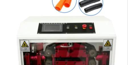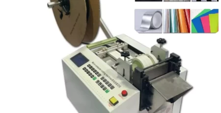
Wire Crimping Machine Issues: Analyzed
What factors contribute to sour connectivity in wire crimping machines?
Relating the root causes of poor contact in wire crimping machines is essential, as it stands as a primary malefactor for malfunctions in colorful bias, from compact smartphones and computers to larger– scale outfit similar as wire crimping machines and aeronautics bias. Given the critical nature of this issue, it demands scrupulous attention. moment, let’s cave into the analysis of contact– related challenges in wire crimping machines, courtesy of perceptivity from the Fortune Sky Terminal Connector Manufacturer.
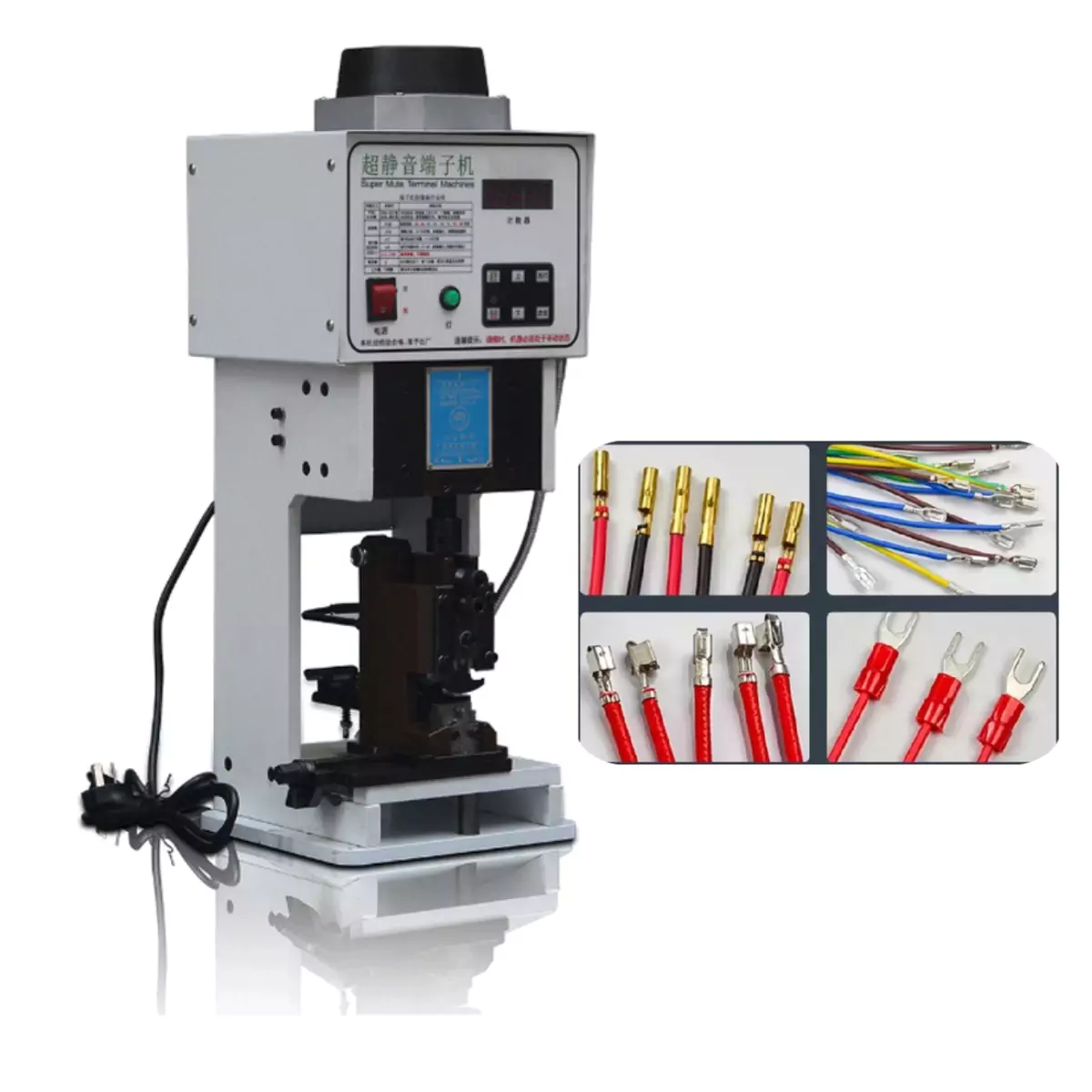
In the realm of computers, conking frequently finds its center in memory modules. still, for wire crimping machines, the crux of poor contact lies within the internal essence operators of the releasing outstations. These factors constitute the heart of the releasing system, easing the transmission of voltage, current, or signals from external cables or lines to the corresponding contact points on the connector.
Due to the consummate significance of these factors, wire crimping machines must meet strict criteria, encompassing stable and dependable contact along with estimable electrical conductivity. Now, let’s explore the myriad factors that can lead to compromised contact structures in wire crimping machines.
Introduction: Understanding Connector Reliability Challenges
Modern automated wire crimping machines face numerous reliability challenges stemming from connector system failures. This technical analysis examines the three primary failure modes affecting electrical connectors – contact issues, insulation defects, and fixation problems – while providing actionable solutions for manufacturing quality improvement.
Section 1: Contact Point Failures – The Weakest Link
Root Causes of Contact Degradation
Structural Design Flaws
Inadequate contact retention force design
Improper mating geometry
Insufficient normal force calculations
Material Selection Errors
Incorrect base metal choices (e.g., brass vs. phosphor bronze)
Suboptimal plating materials (gold vs. tin)
Incompatible spring characteristics
Manufacturing Process Deficiencies
Dimensional tolerances exceeding ±0.05mm
Surface roughness (Ra) > 0.8μm
Improper heat treatment parameters
Electroplating thickness inconsistencies
Performance Impacts
Increased contact resistance (>5mΩ)
Intermittent signal transmission
Voltage drop exceeding 3% of rated value
Current carrying capacity reduction up to 40%
Section 2: Insulation System Failures
Critical Insulation Requirements
| Parameter | Industrial Standard | Failure Threshold |
|---|---|---|
| Dielectric Strength | 1000V/mm | <500V/mm |
| Insulation Resistance | 10⁹Ω | <10⁶Ω |
| Comparative Tracking Index | 600V | <250V |
| Water Absorption | 0.1% | >0.5% |
Common Failure Mechanisms
Material Contamination
Metal flash from molding (>0.2mm particles)
Solder flux residues
Mold release agent accumulation
Environmental Degradation
Moisture absorption (>0.3% by weight)
Fungal growth in humid environments
Thermal aging at >105°C continuous
Processing Defects
Voids in insulation walls (>0.1mm diameter)
Incomplete mold filling
Weld lines in critical areas
Section 3: Fixation and Mechanical Stability Issues
Connector Retention Failure Modes
Primary Locking Mechanism Failures
Housing latch strength <50N
COP (Change of Point) in mating cycle >1000
Wear particle generation >5mg/1000 cycles
Secondary Locking Problems
CPA (Connector Position Assurance) failure
TPA (Terminal Position Assurance) displacement
Backout force <15N
Terminal Fixation Issues
Retention force variance >±20%
Primary lock bending stress >500MPa
Secondary lock engagement depth <0.5mm
Consequences of Fixation Failures
Intermittent connections during vibration
Complete circuit interruption
Arc damage at separating contacts
Overheating at high current applications
Section 4: Quality Control Solutions
Advanced Detection Methods
Automated Optical Inspection
5MP camera systems with 10μm resolution
Machine learning defect recognition
100% inline inspection capability
Process Monitoring
Real-time mold pressure tracking (±1Bar)
Plating thickness measurement (XRF)
Dimensional verification (laser micrometer)
Environmental Testing
85°C/85% RH damp heat testing
50G mechanical shock verification
Vibration testing 10-2000Hz
Section 5: Design Improvement Strategies
Contact System Enhancements
Finite element analysis for stress optimization
Cross-section design validation
Fretting corrosion simulation
Material Advancements
Liquid crystal polymer insulation
Nanocomposite dielectric materials
High-performance contact platings
Manufacturing Process Controls
Six Sigma process capability (CpK>1.67)
Automated process adjustment systems
Statistical process control charts
Conclusion: Building Reliability into Connector Systems
By addressing these failure modes through:
Robust design validation
Precision manufacturing controls
Comprehensive testing protocols
Manufacturers can achieve:
→ 99.9% connector reliability
→ <50ppm defect rates
→ 10-year service life guarantees
Implement these solutions today to eliminate connector failures in your wire crimping operations. [Contact our engineering team] for customized reliability improvement programs.
Find expert wire crimping machine technical resources on our specialized page.