How to Troubleshoot Common Impediments in Wire Splicing Machine Operation?
Common Impediments in Wire Splicing Machine Operation: Causes and Treatments
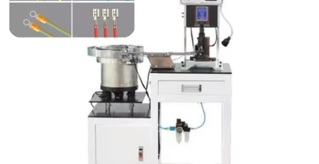
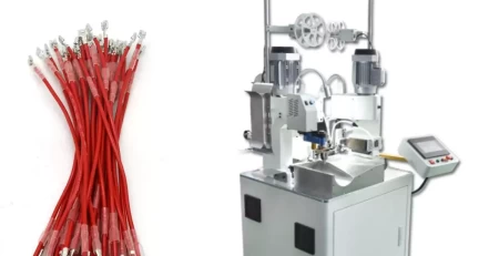
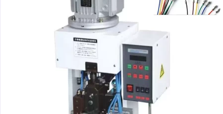
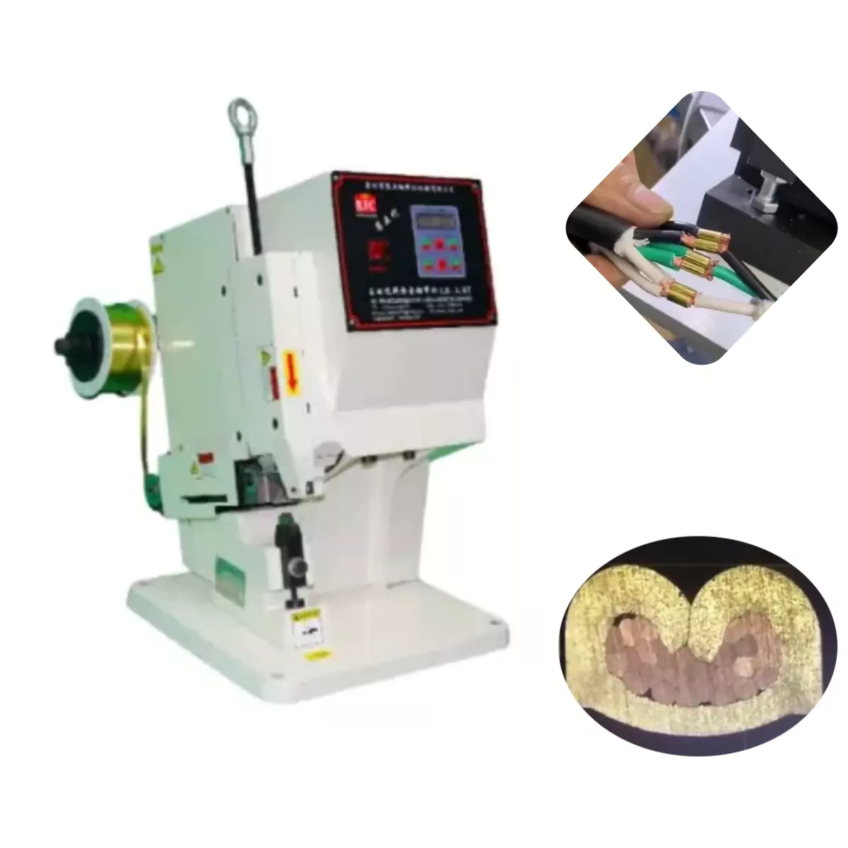
For nearly a decade, our company has relied on wire splicing machines to crimp automotive air conditioner clutch coil leads. Over time, we’ve encountered several recurring issues that, if left unaddressed, can hinder production efficiency. This article outlines these challenges, along with their causes and potential solutions, for future reference.
1. Incomplete Wire Wrapping:
Insufficient Delivered Material: This leads to an uneven U-shape, with one side shorter than the other. Fortunately, this is a straightforward issue to resolve. When the delivered length is slightly inadequate, a simple solution is to gently pry open the delivery wheel’s spring-loaded opening. This increases the wheel’s outer diameter, thereby extending the delivery length.
U-Shaped Copper Strip Tilting During Descent: When the U-shaped strip lands on the lower die at an angle, it can prevent proper wire wrapping or gripping. This can occur for four primary reasons:
- Excessive lubrication on the punch and outer sleeve, causing the U-shape to stick.
- Burrs or scratches present on the punch outer sleeve.
- A significant height difference between the two legs of the U-shape.
- An improperly positioned lower die, creating a large gap between the upper and lower dies, causing the U-shape to tilt.
Unstable Delivery: When the copper sleeve on the delivery wheel exhibits excessive wear, delivery becomes unstable. This can be easily identified by manually checking both delivery wheels for an unusually large gap. If a gap is present, replace the copper sleeve promptly.
- Table 1: Applicable Cross-Sectional Area of Dies
Die Code Punch Thickness (mm) Punch Length (mm) Applicable Cross-Sectional Area (mm²) 02 1.98 57 0.2-0.52 01 2.54 57 0.4-0.81 10 2.89 57 0.81-1.75 20 3.33 57 1.32-3.33
2. Subpar Formation:
Worn Lower Die: A worn lower die can lead to poor formation of the U-shape.
Gap Between Large Edge Cutter and Punch Outer Sleeve: This gap creates substantial burrs at the U-shape’s cut-off point, hindering proper wire gripping and potentially causing cutter jamming. This issue can be readily addressed by loosening the large cutter, carefully tapping it inwards to eliminate the gap, and then retightening it.
Die-Wire Cross-Section Mismatch: The die selection should strictly follow the machine manual’s die table. If there’s a mismatch, replace the die with the appropriate one. Fortunately, some manufacturers offer non-standard dies like 2.7 and 3.07 to better accommodate various wire gauges.
3. Cutter Jamming and Burrs:
Misalignment Between Upper and Lower Dies: Misalignment causes uneven pressure, leading to burrs and cutter jamming. To rectify this, tighten the lower die towards the side producing burrs to eliminate them.
Lower Die Wear: A worn lower die can also contribute to cutter jamming.
Excessive Tensile Force: Overtightening can cause rapid wear on machine components. The tensile force for crimping terminals should adhere to national and international standards and not be arbitrarily increased.
- Table 2: National Standard Tensile Force Values
Conductor Cross-Section (mm²) Tensile Force (N) 0.50 50 0.75 80 1.00 100 1.50 150 2.50 200 4.00 270 6.00 450 10.00 500 16.00 1500 25.00 1900 35.00 2200 ≥50.00~120.00 2700 Excessive Delivery Length: Too much material being squeezed on both sides can cause cutter jamming and burrs. In such cases, verify if the delivery length is excessive or the adjustment is too tight. Often, shortening the delivery length can solve the issue. Additionally, applying a small amount of white oil for lubrication can sometimes alleviate cutter jamming. From a practical standpoint, a slightly wider lower cutter might be preferable. In our experience, using the 02 upper cutter with the 01 lower cutter effectively addressed the jamming issue while maintaining good crimping results.
4. Loose Crimping and Insufficient Tensile Force:
Worn Copper Sleeve: When adjusting the tensile force, if it cannot be further tightened, it signifies excessive wear on the copper sleeve, preventing the punch from descending. In such instances, replace the copper sleeve immediately. Continued use might damage the equipment, potentially causing spindle breakage. This occurs because the upper die would likely already be firmly in contact with the lower die, hindering machine operation.
Crimping Specific Wire Types: Enamelled wire and lead wires (multi-strand soft wires) require an overlapping configuration to achieve sufficient tensile force.
Crimping Wires of Disparate Diameters: When crimping wires with significantly different diameters, pay close attention to their front and rear positions, as well as the delivery length. Place the thicker wire at the front and the thinner wire at therear. The delivery length should be adjusted to create a longer U-shape at the front and a shorter one at the rear. This ensures proper wrapping and increased tensile force. Otherwise, the thinner wire section might not be securely wrapped.
5. Delivery Issues:
Delivery Tube Position: The delivery tube should be positioned as close to the delivery wheel as possible, without causing wear. Improper positioning can lead to delivery problems.
Delivery Wheel Rotation: The copper strip wheel must rotate smoothly. If it gets stuck, slippage might occur, hindering material delivery. Occasionally, improper copper strip