Optimize Insulated Terminal Crimping By Rail! Fix Flow Issues
Optimize Insulated Terminal Crimping By Rail! Fix Flow Issues
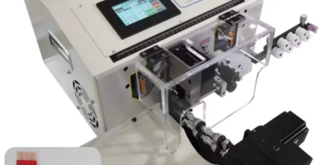
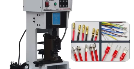
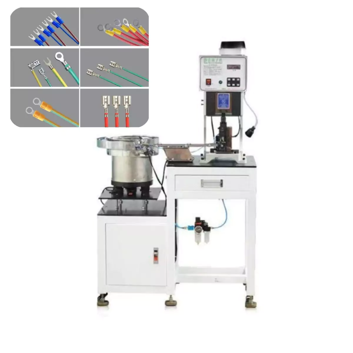
This guide addresses common challenges encountered with rail feeding insulated terminal crimping machines. By understanding these issues and implementing the following optimization tips, you can ensure a smooth and consistent flow of materials for efficient crimping operations.
Common Issues and Solutions
Feeder Not Functioning:
Cause: Insufficient power supply voltage, cracked wiring, blown fuse, burnt coil, improper coil gap, jammed components, or feeder colliding with other equipment.
Solution: Verify power supply, inspect wiring and controller for damage, replace blown fuses, and ensure proper clearance for the feeder. Address any jammed parts and avoid collisions.
Weak or Irregular Feeding:
Cause: Cracked springs, thin base plate (less than 1.5 inches), improperly installed mounting table, uneven mounting surface, debris inside the feeder, excessive coil air gap, machine cycle speed too fast, unstable power supply, part issues (oversized, bent, oily), loose or misaligned feeder screws, too many parts being fed, improper base adjustment, or material change.
Solution: Replace cracked springs. Ensure the base plate has sufficient thickness to prevent vibration absorption. Mount the feeder securely on a level and rigid table with proper support for cylindrical feet. Clean debris from the feeder and minimize the coil air gap. Adjust the machine cycle speed or controller settings as needed. Address any part issues or use compatible materials. Tighten loose screws and adjust the feeder base if necessary. When changing materials, readjust the feeder surface and base for optimal performance.
Issues with Compressed Air (if applicable):
Cause: Unstable air pressure, contaminated air source (water or oil), or rigid air pipes.
Solution: Ensure a clean and dry air source with consistent pressure, regulated by independent filters. Use flexible hoses for improved feeding efficiency.
Additional Considerations for Optimal Performance
Controller Frequency: The controller frequency (half-wave/full-wave selection) can impact feeding performance. Adjust the amplitude to a range where parts begin to move (around 35-40% of full scale) and gradually increase if necessary.
Spring Plate Adjustment: If satisfactory feeding is not achieved at 80% amplitude, follow these steps:
Loosen a spring plate fixing screw slowly to observe changes in feeder speed. If it speeds up, remove the thinnest spring plate from that set (refer to the attached table for replacements).
Add more spring plates if there’s insufficient elasticity, but ensure all spring plates in a set are the same quantity for smooth feeding.
Over time, spring plates can harden. Check vibration if necessary.
Spring plate fractures (usually at the bottom or support top) can occur. Remove a suspect plate and strike it against a hard object to see if it fractures. Replace any fractured plates.
Ensure screws have sufficient length to properly tighten the spring plates. Use grade 5 bolts for lasting hardness.
Additional Notes:
Weld cracks in specific vibrator parts (installation flange, spiral track, return plate bottom, suspension straps, side walls, return material area) can affect vibration frequency and often cause noticeable noise. Address any cracks promptly.
Re-tighten loose rubber feet to prevent resonance drift.
Ensure a firm connection between the top plate and the vibrator. Use a lever or torque wrench for repositioning and avoid pulling the top plate outward. A level top plate is crucial for smooth feeding.
Shims between spring plates play a vital role and should not be overlooked when replacing them. Missing shims can hinder proper feeder adjustment.
Insecurely fastened rubber feet can also affect feeding performance.
If the feeder uses chutes or linear tracks relying on its driving force, consider using an independent linear drive unit to avoid potential side effects.
Multiple “dead spots” in the feeder might require checking diagonally opposite corners for issues like unbalanced weight, improper coil air gap, weld cracks, spring plate fractures, or loose fixing bolts.
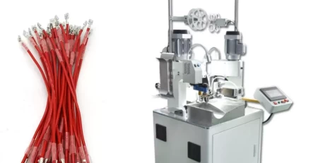
By following these guidelines and addressing potential causes, you can effectively optimize your vibratory feeding system for a smooth and efficient flow of materials in your insulated terminal crimping machine.